
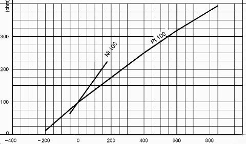
The working principle for metal resistance thermometers, normally called thermoresistances, is bases on the variation of the electrical resistance of a metal with variations in the surrounding temperature.
In the industrial field the materials most frequently used are platinum and nickel which, due to their high resistivity and stability, permit the production of thermoelements which are highly reproducible, small and with excellent dynamic characteristics.
The temperature measurements carried out with thermoresistances are far more precise and reliable than those carried out with other types of sensor such as thermocouples or thermomistors.
Normally resistance thermometers are identified with the code of the material used to construct them (platinum = Pt, nickel = Ni etc.) followed by their nominal resistance at a temperature of 0°C .
TERMOTECH manufactures platinum resistance thermometers which comply with the international standard EN 60751; sensitive elements which conform to other standards, for example JIS C 1604 etc., may be supplied on request.
According to standard EN 60751 the platinum used for the manufacture of resistance thermometers should have a temperature coefficient of
alfa = 3,851x10-3
Standard EN 60751 allows for thermoresistances with a nominal value at 0 °C (Ro) of between 5 and 1000 ohm; however, the values most commonly used are 100 ohm, 500 ohm and 1000 ohm.
The equation linking resistance at temperature t° (Rt) and resistance at 0° (Ro) is a follows:
in the range -200°C / 0 °C
Rt = Ro [ 1+At+Bt2+C (t-100) t3 ]
in the range 0 °C / 850 °C
Rt = Ro (1+At+Bt2)
Where the coefficients A, B and C have the following values:
A = 3,9083E-3
B = -5,775E-7
C = -4,183E-12
The classes of precision for platinum resistance thermometers refer to temperature and are standardized as follows:
Class AA = 0,1+0,0017* | t | (°C)
Class A = 0,15+0,002* | t | (°C)
Class B = 0,3+0,005 | t | (°C)
Class C = 0,6+0,01 | t | (°C)
The temperature ranges of validity of the tolerance classes above mentioned are reported in the table below.
All the resistance thermometers of tolerance class better then class B shall have three or four wire configuration.
Nickel resistance thermometers are standardized by the German Standard DIN 43760.
As opposed to platinum, nickel has a higher temperature coefficient (alpha= 6,17E-03) which, compensating for its lower electrical resistivity, makes its sensitivity comparable to that of platinum thermoresistances.
Their poor resistance to oxidation limits the range of use of nickel resistance thermometers to temperatures between -100°C e +200°C.
The equation linking resistance at temperature t° (Rt) and the resistance at 0° (Ro) is as follows:
in the range -60°C / +180°C
Rt = Ro (1+ At + Bt2 + Ct4)
Where the coefficients A, B and C have a value of:
A = 5,845E-03
B = 6,650E-06
C = 2,805E-11
There is only one class of precision for nickel resistance thermometers in the standard which refers to temperature:
in the range -60°C / 0°C: 0,4 + 0,028 | t | (°C)
in the range 0°C / 180°C: 0,4 + 0,007 | t | (°C)
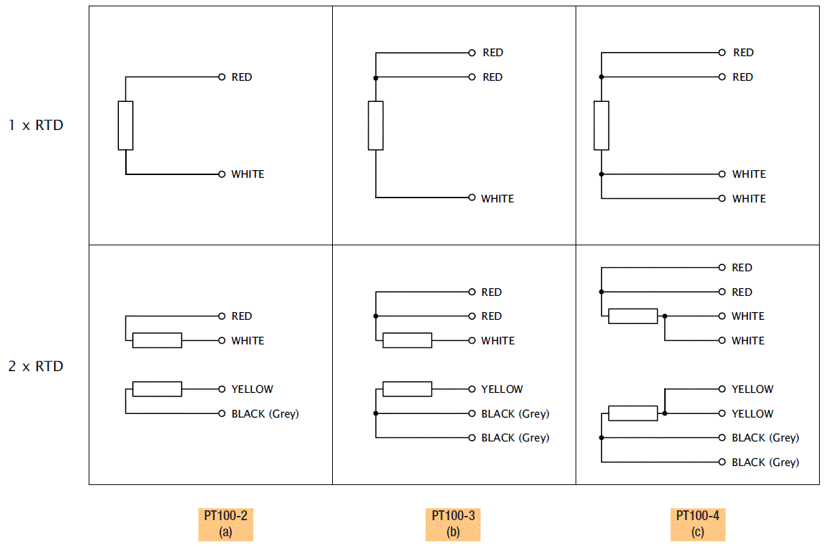
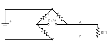
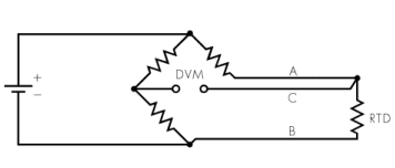
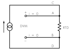
There are different methods for connecting the resistance thermometers to the measuring devices, the choice of one method rather than another basically depends on the precision required in the measurement.
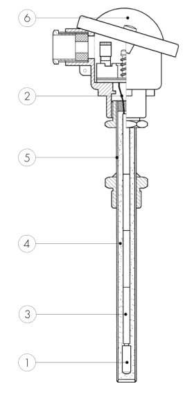
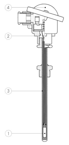
There are two construction types of thermoresistances: with traditional insulation or mineral MgO insulation.
The following table shows the main characteristics of the two types:
| # | Response speed | Electrical Insulation | Vibration resistance | Pressure resistance |
|---|---|---|---|---|
| Traditional insulation | Good | Excellent | Good | Good |
| Mineral (MgO) Insulation | Excellent | Good | Excellent | Excellent |
Traditional insulation thermoresistances comprise:
Measuring temperature with thermoresistances is quite simple to carry out compared to that using other types of sensors, however certain steps should be taken to remedy any measurement errors. There are three main causes of errors introduced into temperature measurements with thermoresistances:
The sensitive element heats up by itself during measuring when it is crossed by a current which is too high which, due to the Joule effect, increases the temperature of the element.
The increase in temperature depends both on the type of sensitive element used and the measuring conditions.
At the same temperature, the same thermoresistance will heat up by itself less if placed in water rather than air; this is due to the fact that water has a higher dispersion coefficient than air.
Normally all measuring devices which use thermoresistances as sensors have an extremely low measuring current, however it is advisable never to exceed a measuring current of 1 mA (EN 60751).
For the correct measurement with thermoresistances it is very important that the electrical insulation between the conductors and the external sheath is sufficiently great, particularly at high temperatures.
The insulation resistance may be seen as an electrical resistance positioned parallel to those of the sensitive element.
It is, therefore, clear how, at a constant temperature, should the electrical insulation diminish, the voltage measured across the sensitive element will also diminish thus introducing an error into the measurement.
Insulation resistance can fall when the probe is used at temperatures which are too high, when there are strong vibrations or because of the influence of physical or chemical agents.
The immersion depth of the sensitive element is also extremely important for correct measurements; unlike in thermocouples where measurements can be considered punctiform, if the depth is not sufficient it can cause errors in the measurement of as much as several degrees °C.
This is due to the fact that the sheath, usually metallic, with which the sensitive element is protected disperses heat in proportion to the difference in temperature between the hot and cold areas; we, therefore, have a thermal gradient along part of the sheath's length.
The immersion depth must, therefore, be sufficient so that the sensitive element inside the sheath is not subjected to this thermal gradient.
The minimum depth will depend on the physical measuring conditions and the dimensions of the thermoresistance (length of the element etc.).
| °C | 0 | -10 | -20 | -30 | -40 | -50 | -60 | -70 | -80 | -90 | °C |
|---|---|---|---|---|---|---|---|---|---|---|---|
| Ohm | |||||||||||
| 0 | 100,0 | 94,6 | 89,3 | 84,2 | 79,1 | 74,3 | 69,5 | 0 | |||
| °C | 0 | -10 | -20 | -30 | -40 | -50 | -60 | -70 | -80 | -90 | °C |
| °C | 0 | 10 | 20 | 30 | 40 | 50 | 60 | 70 | 80 | 90 | °C |
|---|---|---|---|---|---|---|---|---|---|---|---|
| Ohm | |||||||||||
| 0 | 100,0 | 105,6 | 111,2 | 117,1 | 123,0 | 129,1 | 135,3 | 141,7 | 148,3 | 154,9 | 0 |
| 100 | 161,8 | 168,8 | 176,0 | 183,3 | 190,9 | 198,7 | 206,6 | 214,8 | 223,2 | 100 | |
| °C | 0 | 10 | 20 | 30 | 40 | 50 | 60 | 70 | 80 | 90 | °C |
| °C | 0 | -10 | -20 | -30 | -40 | -50 | -60 | -70 | -80 | -90 | °C |
|---|---|---|---|---|---|---|---|---|---|---|---|
| Ohm | |||||||||||
| -200 | 18,49 | 14,45 | 10,49 | 6,99 | 4,26 | 2,51 | -200 | ||||
| -100 | 60,26 | 56,19 | 52,11 | 48,00 | 43,88 | 39,72 | 35,54 | 31,34 | 27,10 | 22,83 | -100 |
| 0 | 100,00 | 96,09 | 92,16 | 88,22 | 84,27 | 80,31 | 76,33 | 72,33 | 68,33 | 64,30 | 0 |
| °C | 0 | -10 | -20 | -30 | -40 | -50 | -60 | -70 | -80 | -90 | °C |
| °C | 0 | 10 | 20 | 30 | 40 | 50 | 60 | 70 | 80 | 90 | °C |
|---|---|---|---|---|---|---|---|---|---|---|---|
| Ohm | |||||||||||
| 0 | 100,00 | 103,90 | 107,79 | 111,67 | 115,54 | 119,40 | 123,24 | 127,08 | 130,90 | 134,71 | 0 |
| 100 | 138,51 | 142,29 | 146,07 | 149,83 | 153,58 | 157,33 | 161,05 | 164,77 | 168,48 | 172,17 | 100 |
| 200 | 175,86 | 179,53 | 183,19 | 186,84 | 190,47 | 194,10 | 197,71 | 201,31 | 204,90 | 208,48 | 200 |
| 300 | 212,05 | 215,61 | 219,15 | 222,68 | 226,21 | 229,72 | 233,21 | 236,70 | 240,18 | 243,64 | 300 |
| 400 | 247,09 | 250,53 | 253,96 | 257,38 | 260,78 | 264,18 | 267,56 | 270,93 | 274,29 | 277,64 | 400 |
| 500 | 280,98 | 284,30 | 287,62 | 290,92 | 294,21 | 297,49 | 300,75 | 304,01 | 307,25 | 310,49 | 500 |
| 600 | 313,71 | 316,92 | 320,12 | 323,30 | 326,48 | 329,64 | 332,79 | 335,93 | 339,06 | 342,18 | 600 |
| 700 | 345,28 | 348,38 | 351,46 | 354,53 | 357,59 | 360,64 | 363,67 | 366,70 | 369,71 | 372,71 | 700 |
| 800 | 375,70 | 378,68 | 381,65 | 384,60 | 387,55 | 390,48 | 800 | ||||
| °C | 0 | 10 | 20 | 30 | 40 | 50 | 60 | 70 | 80 | 90 | °C |
| Tolerence class | Temperature range of validity °C | Tolerance value °C | |
|---|---|---|---|
| Wire wound resistors | Film resistors | ||
| AA | -50 ÷ +250 | -0 ÷ +150 | ±(0,1 + 0.0017 *| t |) |
| A | -100 ÷ +450 | -30 ÷ +300 | ±(0,15 + 0.002 *| t |) |
| B | -196 ÷ +600 | -50 ÷ +500 | ±(0,3 + 0.005 *| t |) |
| C | -196 ÷ +600 | -50 ÷ +600 | ±(0,6 + 0.001 *| t |) |
| t |= Moduls of temperature in °C without regards to the sign
Special tolerance classes may also be defined for extended or restricted temperature ranger.
| Temp. °C |
0,4+0,07*| t | (°C) 0 °C<t<180 °C 0,4+0,028*| t | (°C) -60 °C<t<0 °C |
|
|---|---|---|
| Ohm | °C | |
| -60 | ±1,00 | ±2,10 |
| 0 | ±0,20 | ±0,40 |
| 100 | ±0,80 | ±1,10 |
| 180 | ±1,30 | ±1,70 |
| t | = Temperature (°C)